Subarticle of DIYing a plug that fits the... | PlayStation development | Published 2022-02-17 17:06:35 UTC
Hey! Made some progress on the project, as promised.
Yesterday's post was written in quite a hurry, so it may not be as comprehensible as I would like it to be. Sorry about that, hopefully this post will fix that.
My intention for this project is to make a fully-working PlayStation parallel port connector to make the console to boot from an external ROM, since there is no easy/cheap way to obtain such connector otherwise. That's why I decided to make my own by combining some scrap materials I have at home with the power of 3D printing.
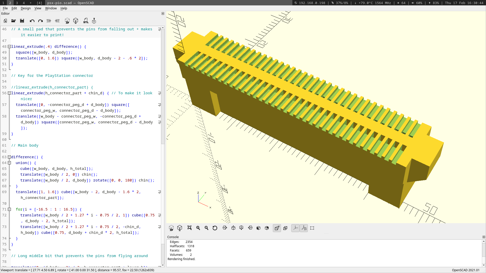
In the previous post, I have only attached some (crappy) pictures of my design, but I haven't shown it in detail yet. To fix that, here are some beautiful screenshots of OpenSCAD, in which I made the model:
This is how it looks from the top. The "fins" are for the pins to exit out of both sides, since there will be an additional piece on the top which will be attached to the sides of this model (there are tabs on either sides, as you can see on the following picture) to keep the pins from falling out.
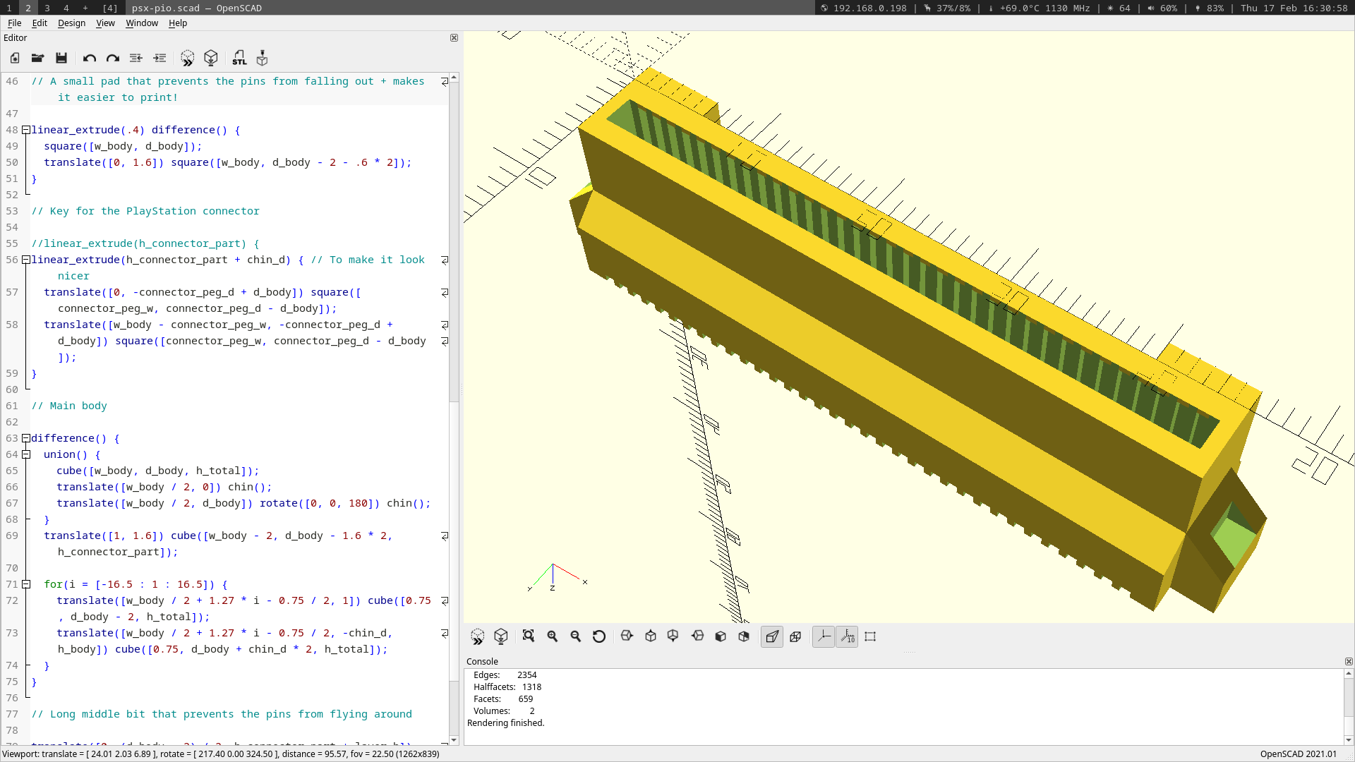
This is the mating part of the connector. It fits into the PlayStation beautifully, and it's keyed, so it is only possible to insert in a single way. And you can also see the tabs on each side for the aforementioned second part of the whole assembly. The inside part of the connector contains guides for the pins so that they stay in place.
It's hard to show a 3D model in detail with just pictures, that is why I put it up on GitHub (which has a built-in 3D model viewer, just click on the "psx-pio.stl" file) as well as its OpenSCAD source code, if you want to give it a try or just want to mess around with it: https://github.com/prochazkaml/PSX-PIO-Connector
Anyway, now that the main part of the entire assembly is finalized (or at least I hope it is), it's time to discuss the actual metal contacts of the connector, which is possibly the most important part of the whole thing. I have settled on small snipped-off LED/resistor/capacitor legs that I have collected over the years:
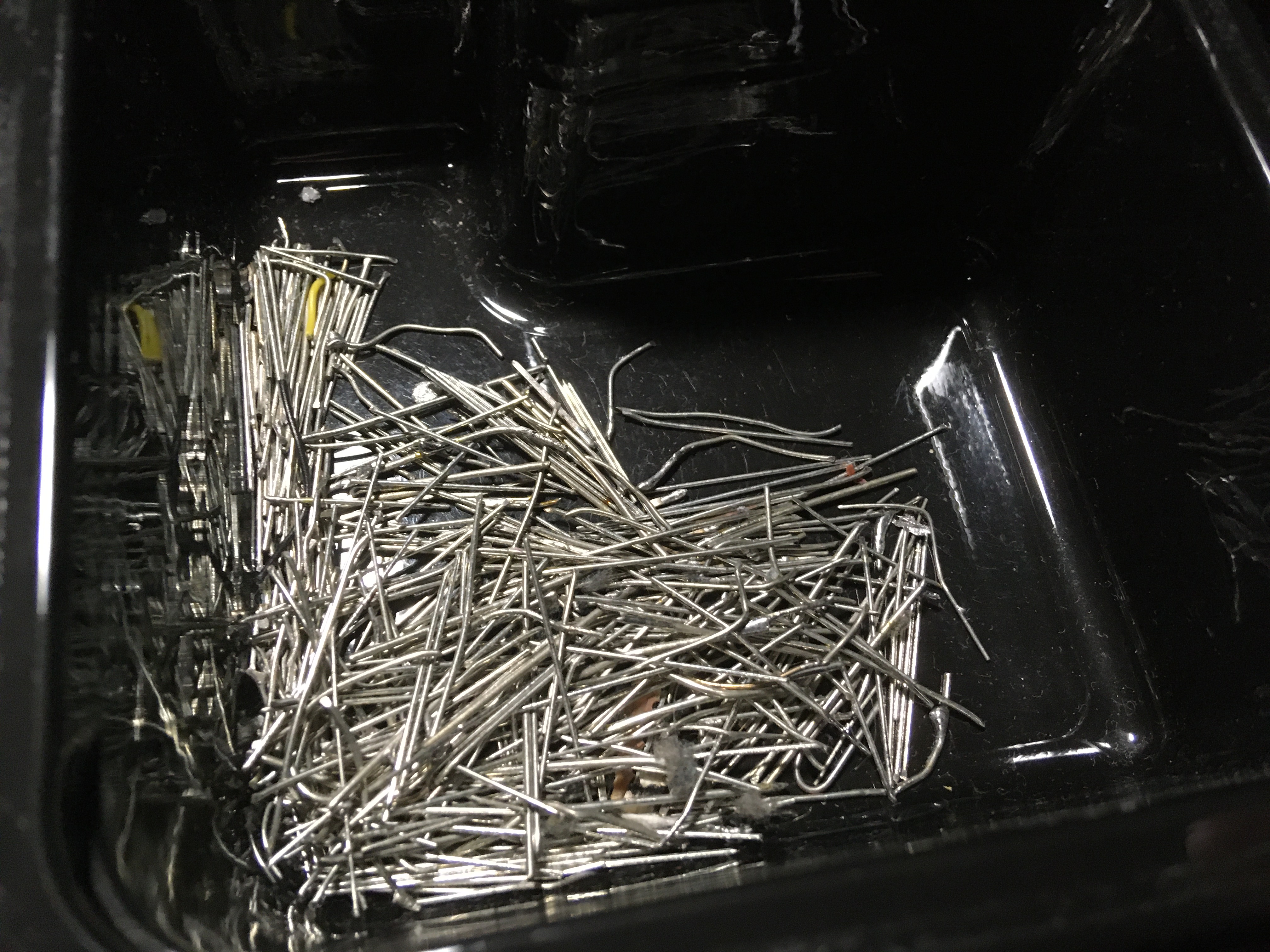
Yeah. I have way more than the 68 needed for the connector. (And as I have mentioned in the previous post, I will not actually need all of them for hooking up a simple ROM, which needs 32: VCC, GND, /CE, /RD, /WR, D0..7 and A0..A18 for a 512k ROM.)
I tried a simple test fit of one of the legs into the connector's body, and it fits prefectly, staying in place even when being moved around. The second part of the connector assembly will add even more rigidity, so I don't really think that the strength will be an issue here.
Here's a short video of me doing just that. I know that the part when I show you the inside of the connector is extremely blurry, appearing almost invisible inside, but trust me, it's in there.
So, that's it for today. Next challenge for tomorrow: make a simple jig for shaping the legs, since straight legs inside the connector won't make any contact, so they have to be slighty bent. And while I'm at it, I'll try to model the second piece of the connector. It will probably require some spring-like mechanism to hold onto the tabs on the side.
See you then, and thanks to all following my little project! 😁
In order to post a comment or reply to one, please log in or create a new account:
0 comments total, 0 shown | Go back to the top