Subarticle of DIYing a plug that fits the... | PlayStation development | Published 2022-03-06 19:20:20 UTC
It's coming closer, I promise. I'll take my PlayStation back apart next week and continue working on the connector and getting it finally working.
In the meantime, I found some Action Replay schematic to see how the ROM is hooked up to the PlayStation's parallel port, and what struck me as being really strange is the fact that the entire cart runs from the PlayStation's 8 V rail, which is then regulated to 5 V inside the cart, which powers the EEPROM (same chip as mine, requires 5 V to operate). That EEPROM then sends data (at 5 V!) back to the PlayStation, which runs at only 3.5 V! I know that the PlayStation has some resistors inside (as I have already mentioned in a previous post), but it is still strange to not use a level shifter for this sort of thing. On the other hand, if it is proven to actually work, I should probably do it the same way.
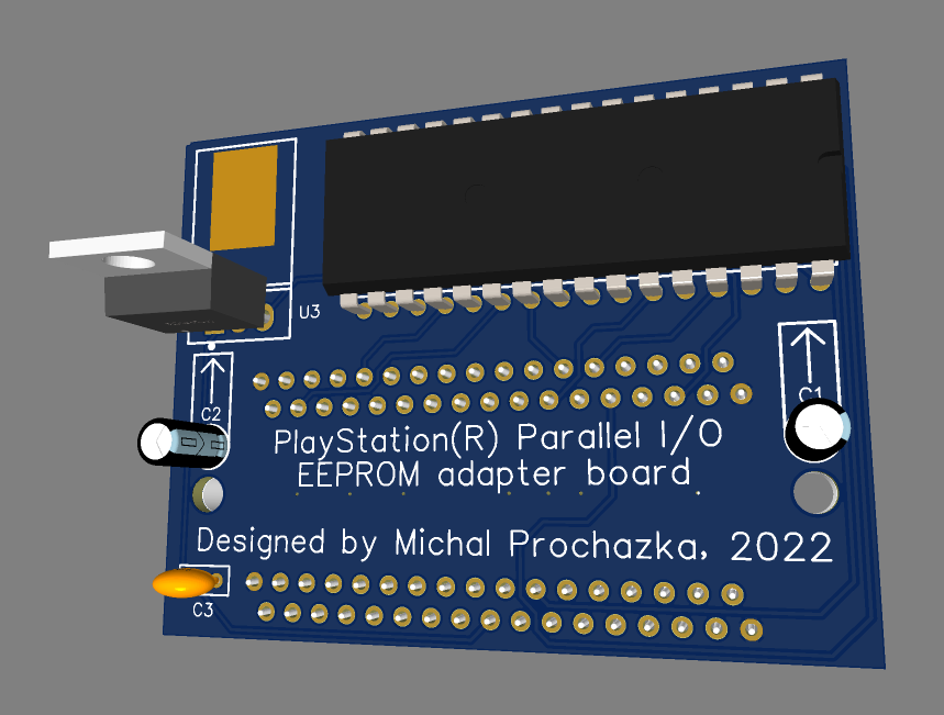
So, I designed a PCB around it! Yay!
Note: the voltage regulator as well as the electrolytic capacitors are supposed to be bent in a way that makes them lie flat against the PCB. And I made sure to have enough clearance around the EEPROM to fit a ZIF socket in there.
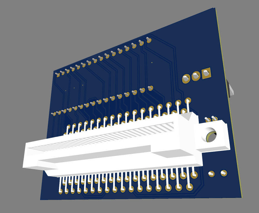
Made in EasyEDA, since that's the only thing I can sort of work with. And it even let me import my 3D model for the connector! Here is the project on OSHWLab in case anyone wants to explore the schematic or the board itself.
Of course, I won't order one until I actually get the EEPROM to boot with my connector. But it's still nice to look into the future, how the project might turn out 😉
In order to post a comment or reply to one, please log in or create a new account:
1 comment total, 1 shown | Page 1
MottZilla (Archived from PSXDEV.net) | Posted on 2022-03-06 19:45:43 UTC
You might want to design a version that does do proper voltage level translation. Often things do work without shifting between 5v and 3.3v levels but it could be causing stress on internal components and if it's in a custom IC that's going to suck if it results in premature failure.
The 3D model looks cool. I suppose a 3D printed casing would follow. Then you've got your whole home made rom cart.
1 comment total, 1 shown | Page 1 | Go back to the top